Card Guides
ETS Alliance offers high-quality Card Guides and PCB Retainers engineered for rugged and mission-critical environments. Our Card Guides provide reliable PCB retention, excellent vibration resistance, and enhanced thermal management. Engineered for superior performance and ease of installation, ETS Alliance retainers outperform traditional wedge-lock solutions, delivering long-term reliability for your electronic systems.
Expertise in Ruggedized Mechanical Hardware
ETS Alliance offers a comprehensive range of rugged PCB Card Guides and mechanical hardware designed for demanding environments:
ZIF style full body mounting design to replace Wedge Lok style Card Guides for VME, VPX, and custom cards
Rugged mechanical Card Guides engineered for high-vibration applications
Mounting hardware optimized for compact enclosures and modular platforms
Designs supporting passive and active cooling to ensure effective thermal management
All our components are rigorously tested and trusted in airborne avionics, mobile ground systems, and industrial automation—where reliability and durability are critical.
ETS Alliance: Engineered PCB Card Guides for Aerospace and Mission-Critical Systems
In aerospace, military, and industrial applications, even the smallest hardware component can be a potential point of failure. That’s why engineers rely on ETS Alliance PCB Card Guides for precision, reliability, and rugged performance.
Our solutions are designed for ATR computing and avionics enclosures, built to withstand extreme conditions encountered in military aircraft and vehicles. Constructed from robust yet lightweight materials like aluminum, stainless steel, and composites, our rugged Card Guides resist shock, vibration, moisture, dust ingress, electromagnetic interference (EMI), temperature extremes, and altitude-related pressure changes—ensuring mission-critical systems operate flawlessly.
ATR computing and avionics enclosures need to be designed to withstand the harsh conditions faced by military aircraft and vehicles. They are typically constructed from robust and lightweight materials such as aluminium, stainless steel and composites, and ruggedized against environmental factors such as shock, vibration, moisture and dust ingress, electromagnetic interference (EMI), extremes of temperature, and changes in pressure due to altitude.

VPX Faces a Heat Dissipation Challenge
Relying only on board edges to conduct heat limits performance. Instead, using the entire board can improve heat management.
In our previous discussion, Embedded Board Standards Are No Longer “Standard” – So Why Aren’t You Looking for Better Alternatives?, we highlighted that VPX has become more of an “open specification,” which reduces its advantages in modularity and interoperability. However, a bigger concern is heat dissipation.
Wedge Locks as Heat Bottlenecks
Most VPX boards are used in conduction-cooled systems. Here, heat—often up to 150W for a 6U card—must travel across the board to the ejectors, or wedge locks, which then transfer it to the chassis. The limited surface area of wedge locks restricts heat transfer, causing potential overheating issues.
Why Modern VPX Boards Struggle
This problem was minor in early VPX systems, where boards dissipated only 30–40W. Today, high-performance boards integrate CPUs, memory, graphics, communications, and I/O, often exceeding 150W. Modern processors like Xeon can consume 85–120W alone. Consequently, traditional wedge-lock cooling is often insufficient for current high-power applications.
The Need for Advanced Card Guides
Therefore, using engineered PCB Card Guides from ETS Alliance helps distribute heat more effectively. These rugged guides support high-power boards, improve thermal management, and maintain reliability even in harsh environments.

Rather than relying on a board’s edges to dissipate heat, the entire board can be used to improve thermal management. For example, in a GMS small form factor system, heat is conducted directly from the board to the chassis base.
We developed a method to integrate the board into a box mounted on the chassis base, as shown in Figure 3. This allows the board’s entire surface to conduct heat through its bottom, effectively acting like a 100% heat pipe that transfers energy directly from the processor to the aluminum frame—bypassing the limitations of a narrow wedge lock.
The key advantage of this approach is the larger surface area for cooling. By transferring heat directly to the chassis or vehicle frame, you ensure efficient thermal management for the electronics without affecting the surrounding cabin environment.
Credit: VPX Has a Heat Dissipation Problem | Military Aerospace
ZIF Rod Displacement Curve Torque Specification

ZIF III Advantages over Wedge Style Board Retainers
Introduction
ZIF III board retainers offer significant advantages over traditional wedge-style retainers. They provide system integrators with improved heat management, easier board installation, and enhanced reliability for mission-critical electronics.
ZIF III Retainer Description
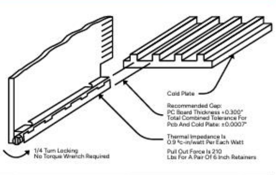
The ZIF III retainer is engineered to secure the PCB along its entire length, ensuring full contact for optimal stability. Once assembled, the board and retainer lock into a cold-wall with a simple quarter turn—no torque wrenches or special settings are required.
Its unique locking design distributes pressure evenly along the PCB edge, improving heat transfer while providing excellent resistance to shock and vibration. The ZIF III is available with both braze and screw mounting options, each offering uniform mounting pressure without causing board warping.
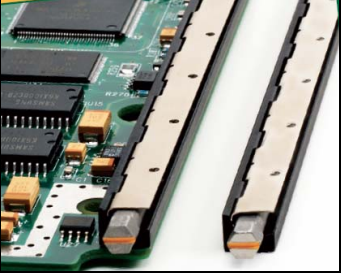
Figure 1: ZIF III Retainer – Mounted and Unmounted
The ZIF III retainer features a quarter-turn lock and unlock mechanism for fast board loading and unloading. A colored slot in the hex-head rod provides a clear visual indication of the retainer’s lock status, ensuring easy and reliable operation.

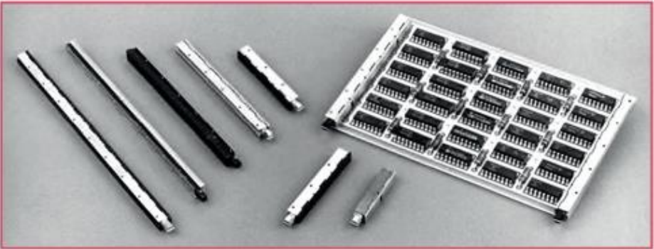
Figure 2: Typical ZIF III Assembly and Cold Plate Mounting
Figure 3 illustrates how the ZIF III retainer distributes force evenly along the PCB, unlike wedge-style retainers that concentrate pressure in narrow bands. This uniform contact maximizes both mechanical stability and heat transfer across the cold wall, as indicated by the arrows.
In contrast, wedge-style retainers can create air gaps and hot spots, reducing thermal efficiency and potentially compromising board reliability. The ZIF III’s design overcomes these issues, ensuring consistent performance in rugged environments.


ETS Electronic Components Page 2 9/28/2006
ZIF III Advantages over Wedge Style Board Retainers AN1017
Conclusion
ZIFIII retainers provide a simplistic quarter-turn lock and uniform clamping pressure. These and other features should be considered for all mission-critical applications.
Referenced Documents
ZIF III retainers are tested and qualified according to rigorous military standards, including:
MIL-STD-810
MIL-E-16400
MIL-S-901
For complete details on ZIF III and other ZIF products, refer to the official documentation.
Written by: Damon Niswonger | Date: 9/28/2006
ETS Electronic Components Page 3 9/28/2006
ZIF III Advantages over Wedge Style Board Retainers AN1017
Ruggedized ATR Military Chassis and ZIF III Board Retainers
Air Transport Rack (ATR) military enclosures play a vital role in protecting critical systems across a wide range of military applications. From fighter jets and transport aircraft to nuclear submarines and advanced battle tanks, these enclosures—available in 1/2 ATR, 3/4 ATR, and Full ATR sizes—are engineered to meet the highest standards of reliability and durability.
When paired with ZIF III board retainers, ATR enclosures ensure secure PCB mounting, improved heat management, and consistent performance even under extreme shock, vibration, and environmental conditions.
Versatile Applications
ATR enclosures are carefully designed to meet the unique requirements of specific systems, applications, and vehicles, delivering reliable performance even in harsh environments. They are essential in scenarios where system reliability is critical, including simulators, ground test systems, and a variety of military vehicles.
When combined with ZIF III board retainers, these enclosures provide secure PCB mounting, enhanced thermal management, and consistent operation under extreme conditions.
Protective Design
ATR chassis are designed to protect internal VMEbus boards and backplanes, ensuring reliable operation even under extreme conditions such as high vibration and temperature fluctuations. These enclosures meet strict EMI/EMC standards, providing robust protection against electromagnetic interference and noise—critical for mission-critical military and aerospace applications.
Paired with ZIF III board retainers, ATR chassis guarantee secure PCB mounting, improved thermal management, and consistent system performance in demanding environments.
Complex Thermal Management
One of the primary challenges in ATR enclosure design is effective thermal management. With multiple high-power circuit boards operating within the chassis, proper cooling is essential to ensure reliable performance.
ATR enclosures often integrate advanced cooling mechanisms to regulate temperatures, prevent overheating, and maintain optimal operating conditions. When combined with ZIF III board retainers, these solutions enhance heat transfer and improve overall system reliability.
ZIF III Board Retainers
At the heart of efficient thermal management in ATR enclosures is the ZIF III board retainer. Its innovative design, featuring zero insertion force and a quarter-turn lock/unlock mechanism, ensures uniform clamping pressure along the chassis sidewall.
This uniform pressure maximizes thermal conductivity, which is especially important given the tight VMEbus board spacing (0.8″ pitch) in ATR enclosures. With a low thermal resistance of 1.2°C-In/W, the ZIF III retainer efficiently transfers heat to the cold plate, supporting reliable system operation under demanding conditions.
Conclusion
ATR military enclosures and ZIF III board retainers are essential for protecting and optimizing the performance of critical military systems. By effectively addressing challenges such as thermal management and electromagnetic compatibility, these rugged solutions meet the stringent requirements of modern defense applications.
Their reliability and versatility make them indispensable across a wide range of military platforms, ensuring consistent operational performance even in the most demanding environments. For more information on ATR military chassis and ZIF III board retainers, visit ETS Alliance.
ZIF III Board Retainer Features
| Parameter | Features |
|---|---|
| Insertion and Extraction | Zero insertion force |
| Cold Plate | Excellent heat transfer |
| Clamping Pressure | Uniform pressure along the PCB edge |
| Locking/Unlocking | 1/4 turn lock/unlock |
| Operation Repeatability | Consistent and easy to operate |
| Over-torque Sensitivity | Not susceptible to over-torque |
| PC board operational damage | Does not damage PC boards |
| Retainer Mounting Options | Screw mounting |
| Thermal Performance | 12°C-inch/Watt |
ZIF III Board Retainer Common Sizes
| VMEbus Card Size | ZIF III Retainer Size | CTS Standard Part No. |
|---|---|---|
| 9U Size D | 12" (2 Required) | Z3A12SBSBNL/R |
| 6U Size C | 12" (2 Required) | Z3A12SBSBNU/R |
| 6U Size B | 6" (2 Required) | Z3A60SBSBNU/R |
ZIF III Thermal Resistance
| Thermal Resistance (°C/W/IN) | 10 Watts | 25 Watts | 50 Watts |
|---|---|---|---|
| 1" Length | 1.17 | 0.84 | 0.69 |
| 2" Length | 1.17 | 0.97 | 0.89 |
| 6" Length | 1.16 | 0.93 | 0.84 |
Environmental Qualification Tests
ZIF III board retainers are rigorously tested and qualified to MIL-STD-810 standards, ensuring reliable performance in extreme environments:
High Temperature: Method 501 – 71°C, after 48 hours exposure to 150°C
Low Temperature: Method 502 – -55°C
Vibration: Method 514, Category B.1 – 5 Hz to 2 kHz
Salt Fog: Method 509
Shock: Method 516
These qualifications demonstrate the ZIF III retainer’s durability and suitability for mission-critical military and aerospace applications.
Ruggedized ATR Military Chassis and ZIF III Board Retainers
ATR military enclosures play a vital role in protecting critical systems across a wide range of military applications. From fighter jets and transport aircraft to nuclear submarines and advanced battle tanks, these enclosures—available in 1/2 ATR, 3/4 ATR, and Full ATR sizes—are engineered to meet the highest standards of reliability and durability.
When paired with ZIF III board retainers, ATR enclosures ensure secure PCB mounting, enhanced thermal management, and consistent system performance even under extreme conditions.
DESIGN FEATURE
The ZIF III board retainer offers a combination of performance, reliability, and ease of use:
PC Board Mountable: Designed for direct PCB integration
Positive 1/4 Turn Locking: Quick and secure locking mechanism
Field Maintainable: Easy to service and replace on-site
Quick and Easy Installation: Simplifies board loading and unloading
Superior Mechanical Retention: Ensures reliable PCB stability
Thermally Efficient: Low thermal resistance of 0.9°C-In/W for effective heat dissipation
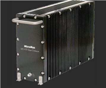
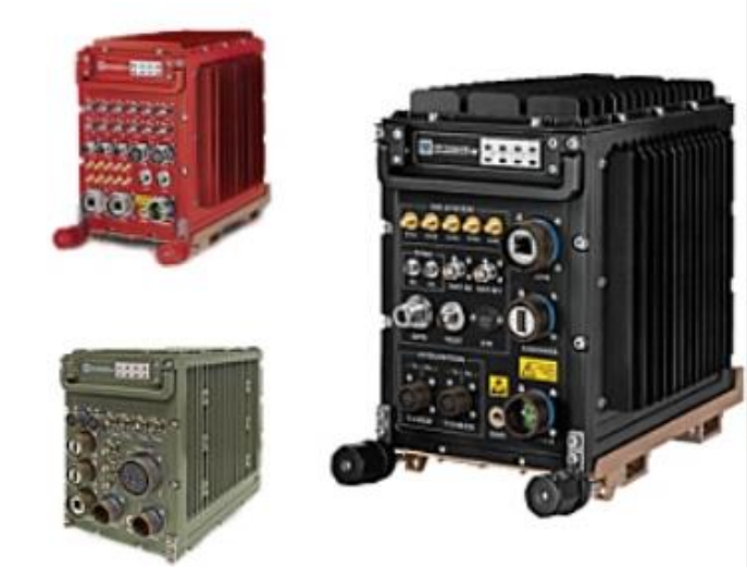
Ruggedized ATR Chassis
ATR computing and avionics enclosures are engineered to withstand the harsh conditions encountered by military aircraft and vehicles. They are constructed from strong yet lightweight materials, including aluminum, stainless steel, and composites, and are ruggedized to resist environmental challenges such as shock, vibration, moisture, dust ingress, electromagnetic interference (EMI), temperature extremes, and altitude-related pressure changes.
These durable enclosures, when paired with ZIF III board retainers, ensure secure PCB mounting, effective thermal management, and reliable system performance even in demanding operational environments.
Built for Environments Where Failure Isn’t an Option
Printed circuit boards (PCBs) used in mission-critical environments—such as aircraft, defense systems, and industrial vehicles—must withstand more than just vibration. They are exposed to extreme temperatures, sustained shock, rapid pressure changes, and tight assembly constraints, making generic hardware inadequate.
ETS Alliance designs thermal- and shock-resistant PCB card holders specifically for these demanding conditions. Their retainers reduce thermal expansion, absorb mechanical stress, and maintain long-term alignment, ensuring consistent reliability even in the harshest operational environments.
Beyond Parts: Engineering-Driven Collaboration
ETS Alliance goes beyond off-the-shelf hardware by working closely with clients to adapt or co-design solutions for specific applications. Their services include:
Thermal Analysis and Mechanical Design Consultation – optimizing heat management and structural performance
Fitment Solutions for Custom Card Profiles – ensuring precise integration with unique systems
Reverse-Engineering of Legacy Components – supporting upgrades and replacements
Prototype-to-Production Scaling – from initial concept to full-scale deployment
For defense contractors, aerospace integrators, and system engineers managing long program timelines or retrofits, ETS Alliance provides not just hardware, but engineering-backed solutions that ensure reliability, performance, and compatibility.
Reliability in Aerospace and Defense
ETS Alliance has earned the trust of leading aerospace and defense technology firms. By emphasizing reliability, modularity, and engineering precision, they ensure that critical systems remain operational—even under the most demanding conditions.
Interested in selecting a part or designing a custom solution? Visit ETSAlliance.com to start the conversation and explore how ETS Alliance can support your project.